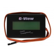
We are proud to introduce a new throttle governor developed and flown by Multi-time World Champion Curtis Youngblood. This Dual Mode Governor features simply push button setup, rpm indication lights, and a small slim case. Compatible with G-view display
Modes of Operation
Basic mode- a simple, quick start option for setting up the ATG. Set the rpm range via push button and indication lights and go fly. Nothing but basic curves needed.
Active Throttle Mode- Much more than just a limiter. In Active Mode ATG allows you to run your throttle curves and mixes to optimize engine performance, while still governing to to a set RPM. ATG passes through all your throttle curves and mixes and simply modifies that signal as needed to keep your set RPM.
Note! When going through initial setup please do Quick setup (steps 1- 12) first. See product info below for instruction corrections. See Tech specs for setting ATG V1 with G-view.
Note!! ATG is rated up to 12V
Product Information
Active Throttle Governor
Instructions:
ATGv3 Instructions
Instruction Corrections and Notes:
Futaba Channel Notes:
9z with 9 channel Futaba Reciever
Use Throttle in Channel 3 (default)
ATG RPM control (wire with Blue Heat Shrink) in Channel 5
ATG RPM control (wire with Blue heat shrink) can be used in Channel 7 as long as Channel 3 and Channel 7 travel set to 100/100 or less.
12mz and 14mz with 9 channel Futaba Reciever.
Use Throttle in Channel 1(default)
ATG RPM control (wire with Blue Heat Shrink) in Channel 3 or Channel 9
12mz and 14mz with G3 Futaba Reciever
Use Throttle in Channel 1 (default)
Use ATG RPM control (wire with Blue Heat Shrink) in Channels 10 or 11
Checking the Sensor - on futaba equipment you will need to be in throttle kill when checking the sensor light. On JR you just need to be at low throttle stick and low trim.
General notes:
a.) When going through initial setup please do Quick setup (steps 1- 12) first. Detailed instructions are not in proper order for step by step setup.
b.) Checking the magnet direction cannot be done until after setting the "L" and "H" button in steps 8 and 9 of the quicksetup. If "L" and "H" have not been set you will simply get a solid red light. So we recommend completing steps 1-12 of the quick setup first and then checking magnet direction/ install magnet.
c.) The Lights/RPM setting information on the included card is incomplete. Up to 1950 RPM the card is correct. But it says at 2000 the lights change to fast flashing this is incorrect. See below for the corrected chart.
RPM Lights
1600 green flashing fast
1650 1 green flashing
1700 2 green flashing
1750 3 green flashing
1800 1 red - 1 green flashing
1850 1 red flashing
1900 2 red flashing
1950 3 red flashing
2000 4 red flashing
2050 5 red flashing
2100 6 red flashing
2150 7 red flashing
2200 red fast flashing
Setting Up ATG with the Futaba 14MZ with G3 reciever
The ATG requires that the throttle and Aux (RPM Set) pulses arrive at different times.
With the Futaba 14MZ the signals to the servos from Channels 1-3, 7-9 and 14 (Group A) all are sent at the same time. The signals from channels 4-6 and 10-13 (Group B) are sent at a different time.
Thus with the ATG the throttle and Aux(RPM) channels must be from different groups.
The default throttle channel in the Futaba is Channel 1, and Channels 4-6 are normally used for Aileron, Elevator, and Collective.
With the ATG, the governor function can be assigned to any of the available channels in Group B. We have actually used channel 10 and 11 for this and it functioned fine.
The procedure we used is as follows:
Go to the Linkage Menu
Function
Assign an unused Aux channel to Channel 7 (normal governor channel).
Assign Governor to Channel 11
End Point (ATV)
For Channel 11 set both limits to 155%
Leave travel Adjust at 100%
Go to Model Menu
AFR(D/R)
Select Governor and Make Sure Rate A & B set to 100%
Governor
Set switch condition for each rate
CH 11 AFR(D/R) 100 100
Limit 155 155
Travel 100 100
If you set Governor mode to read RPM for the Futaba governor, the ATG RPM is as follows:
Futaba ATG
2100 2200
2015 2200
2010 2190
2005 2180
1990 2150
1960 2100
1935 2050
1905 2000
1875 1950
1850 1900
1820 1850
1790 1800
1765 1750
1735 1700
1710 1650
1680 1600
1655 1550
1625 1500
1595 1450
1570 1400
1560 Off
1470 Off
JR PCM 10X Setup with stunt modes
Using one of the curve mixes (Mixes 5 - 8) can mix GEAR->AUX2 (or whatever you choose as your Aux channel). Then push the page button twice. This gets to the page that lets you set the "Master" for this mix. If you push the "SEL" button once in changes fron NORM to INCL. If you push it again it changes to ORIG. And if you watch the mix changes from GEAR->AUX 2 into #FMOD-AUX2.
What this now means is the flight mod switch now controls this mix. If you hit the page button again to get back to the first page, you can see the curve. As you flip the idle up and throttle hold switches the vertical line moves to different positions on the curve. All you need to do is store points for each of these positions and then raise or lower the curve to change the RPM. So you now have control of RPM using the stunt mode (idle up) switches.
The only other thing to do is go to the second page on the mix menu by hitting the page button again. On this page you can select when you want this mix on or off. I just turn the mix "ON" all the time.
Technical Information
ATG is rated up to 12V operation.
NOTE: When going through initial setup please do Quick setup (steps 1- 12) first. Detailed instructions not in proper order for step by step setup.
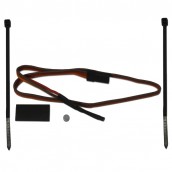
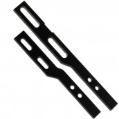
ATG - uses a hall affects sensor to monitor Engine RPM (compatible with Throttle Jockey) Note: it is not compatible with CSM sensors!! Comes with all hardware needed to use on 30 -90 size glow powered machines.
How to tell the difference between ATG V1 and V2
1.) V2 has a small blue dot on the packaging with a “2” on it. V1 does not.
2.) V2 has an addendum sheet included on the box titled “ATG version 2 Instruction Addendum”
3.) The unit themselves look the same, but they behave slightly different in programming so you can tell the difference.
a.) After going through the quick setup, move the throttle to full low (make sure the throttle curve is full low, not just the stick). Now push the “P” button. This gets you into mode selection. Now push the “H” button.
1a.) ATG V1- has two options, light off=normal mode, Fast red/green flashing=Active mode.
2a.) ATG V2 – has three options, light off=normal mode, slow red/green flashing=dual model, fast red/green flashing=active model.
b.) V1 and V2 get into the display mode differently. With V1 you hold down the “P” button while turning on the receiver. But with V2 you turn on the reviever first and then hold down the “P” button for 6 sec to get into display mode (just like the Solid G)
Using the G-View Display with ATG V1
To get into Display mode with ATG V1
1.) plug the display into the ATG (the plug slot furthest from the servo and AUX wires).
2.) Now push the “P” button while switching on the receiver (make sure your transmitter is on already)
3.) Release the “P” button and the display will switch to the first parameter listed below.
4.) The only items of interest are highlighted below with **
ATG V1
Sfreq
199
- Ignore
Test
224
- Ignore
GrRat **
85
- Gear ratio
85=8.5, 86=8.6, 87=8.7, etc…
GvRPM **
1940
- RPM
Set with radio AUX channel. Cannot be set without AUX Channel
Thrtl**
94
-Throttle position, throttle %
HvTrt
30
- Ignore
ArTrt
40
- Ignore
Curve**
No
-Mode selection
Push “H” for “No”=Normal Mode
Push “L” for “Yes”=Active Mode
Gain
50
- Ignore
ProGn
60
- Ignore
SumGn
35
- Ignore
Dd Gn
60
- Ignore
DdBnd
75
- Ignore
Drvth
17
- Ignore
DrvGn
17
- Ignore
ArRPM
1700
- Ignore
LoTrt**
1841
-Low throttle setting- Cannot be set here
HiTrt**
1142
-High throttle setting- Cannot be set here
NHold
2
- Ignore
Navg
1
- Ignore
Reset
0
- Ignore
Sftwr mg07a
- Ignore
5.) **Parameter details
GrRat – Gear ratio – this shows you the present gear ratio setting. Push “L” or “H” button to lower or raise this setting. Goes on increments of 0.1.
GvRPM – RPM- shows present RPM setting. Adjust this value using the Aux channel on your radio. This cannot be set without the aux channel plugged in (previous instructions saying this can be set without AUX plugged in are incorrect)
Thrt – Throttle position – this represent the % throttle setting. If you get a large number like “65530” that means you are below the low throttle “L” setting. This is fine, just indicates the stick is presently below throttle low on the ATG.
Curve – Mode selection – lets you switch between normal and active modes. Push “H” to switch to Normal Mode “No”. Push “L” to switch to Active Mode “Yes”
LoTrt – Low throttle setting – this is the channel value for the Throttle Low set during the quick setup. This can not be changed while viewing with the G-view.
HiTrt – High throttle setting – this is the channel value for the Throttle High set during the quick setup. This cannot be changed while viewing with the G-view.
6.) For all the items listed as “Ignore” we recommend the user not change those items unless suggested to do so by us to fix any specific performance issues. Overall these parameters should not need to be adjusted.
7.) If you wish to return to default parameters hold down the “L” and “H” buttons while turning on the receiver. This will return the unit to default settings.